This is part 3 in a series about different caches available to Android Gradle projects. In part 1 I wrote about the benefits provided by Gradle’s cache of incremental builds and the build cache directory. In part 2 I wrote about Android’s build cache, the Gradle daemon, and dependency caching. Here in part 3, I write about the deprecation and remove of Android’s build cache, and introduce Gradle’s configuration cache. Continue reading “Understanding Different Gradle Caches for Android Projects, part 3”
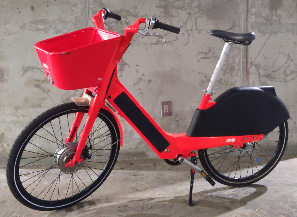
My Saved JUMP Bike
Since initially writing this Lime has started to reintroduce masked JUMP bikes into the Atlanta area.
I recently built up a reclaimed JUMP e-assist bike. These bikes were everywhere in Atlanta. I rented them pretty regularly myself. Eventually JUMP pulled out of Atlanta and these bikes disappeared. Several months afterwards though, I started to notice a few JUMP bikes sitting in abandoned lots and ditches. They had all been picked over. One was missing a front wheel, another a battery. A third bike was mostly frame and rear wheel. I quickly realized that between the three bikes there were enough parts to cobble together a complete bike. This got me down a rabbit hole learning more about these bikes. I had to scrape through lots of bits of information around the web. I also learned a lot about these bikes during the teardown.

Promoting Adaptability Over Estimation
I recently read Jacob Kaplan-Moss’ article Software Estimation Is Hard. Do It Anyway. His argument is that although estimation is hard, there are benefits to getting better at it and being able to provide accurate estimates. I disagree with his argument and propose a more helpful mindset.
Banning Preemptive Sludge Justification
This is a sample of Slack messages I’ve read lately that all share a common theme:
Hi all – I’m getting acupuncture from 11:30 – 12:30 so I’ll be offline during that hour.
Hey y’all, I have a few painters in my house today and tomorrow so I may be intermittently away as I shift my workspace from room-to-room
Good weather outside, so I’m gonna go sit under a tree and read [documentation]. Will be away from Slack for about an hour.
This is my favorite
Wanted to give folks a heads up. My mom (our babysitter) pulled something in her back so she’s not able to watch [kid]. [Spouse] is taking care of it today, but if she’s not better tomorrow I’ll have to take the day off and take over. Might still call into a few meetings here and there.
These messages were posted in channels with 20+ people. Most of the people in these channels were not working directly with the authors; they were not in the middle of a chat conversation and got interrupted. Most of these authors did not have meetings scheduled with any of the other channel members during their absence.
I recently advocated that we ban this type of conversation in Slack. It didn’t go over well. Here’s my defense. Continue reading “Banning Preemptive Sludge Justification”
Android Mapbox SDK: Hiding Labels As User Zooms Out
I’m using Mapbox Android SDK in a side project to show bike paths and points of interest (POI). The POIs are indicated with a marker icon and a text label. I only want to show the labels at certain zoom levels. Mapbox provides some label collision options but none of them work like I want. Here’s how I got this working.
Continue reading “Android Mapbox SDK: Hiding Labels As User Zooms Out”